Which S Parameter is Equivalent to Forward Gain? A Deep Dive into RF Engineering S parameters versus rf frequency
If you are looking for Measurement sample and RF measurement method | Download Scientific Diagram you've came to the right place. We have 25 Pics about Measurement sample and RF measurement method | Download Scientific Diagram like electrical engineering - Control RF wave direction or path, S-parameter simulation results and model structure of the RF waveguide and also 4 Levels to Master in RF and Microwave Engineering – FILPAL XPress. Here it is:
Measurement Sample And RF Measurement Method | Download Scientific Diagram
 www.researchgate.net
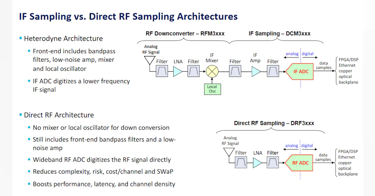
Minimizing The Signal Chain With Direct RF Technology | Electronic Design
 www.electronicdesign.com
RF Engineering Basic Concepts: S-parameters
 studylib.net
studylib.net
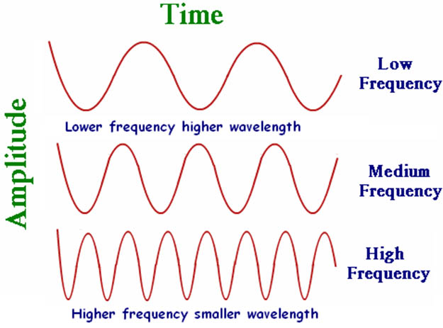
Radiation Charts - Electromagnetic Spectrum (RF Spectrum)
 aktinovolia.com
rf spectrum electromagnetic radiation frequencies radio
S-parameter Simulation Results And Model Structure Of The RF Waveguide
 www.researchgate.net
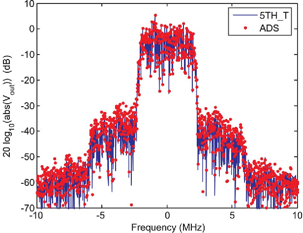
S Parameters Versus RF Frequency | Download Scientific Diagram
 www.researchgate.net
A, RF Waveforms At Each ReVERSE Iteration. B, Reduction Of Peak RF
 www.researchgate.net
4 Levels To Master In RF And Microwave Engineering – FILPAL XPress
 filpal.wordpress.com
Simulation S-parameter Results Of Designed RF Feed Through | Download
 www.researchgate.net
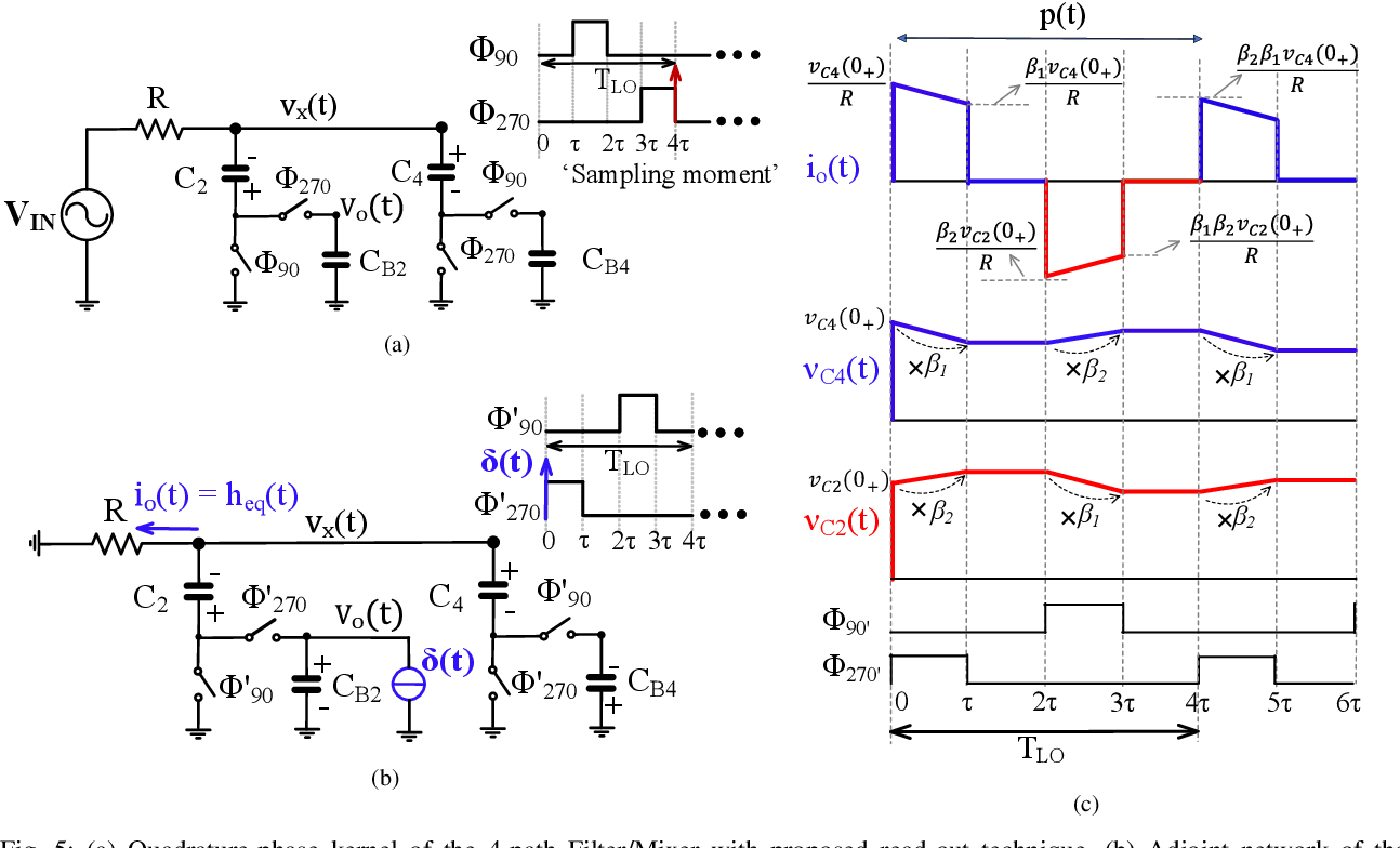
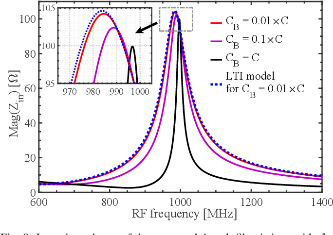
Figure 10 From A Fully Passive RF Front End With 13-dB Gain Exploiting
 www.semanticscholar.org
RF Propagation Sections Flashcards | Quizlet
 quizlet.com
Forward RF Power As A Function Of Q Ext At The Design Operating
 www.researchgate.net
Figure 1 From Design Of A Power-Amplifier Feed-Forward RF Model With
 www.semanticscholar.org
What Are S-parameters - Simple Explanation - RF Page
 www.rfpage.com
rf explanation
Question 5. [20 Points] An RF Transmitter Consists Of | Chegg.com
![Question 5. [20 points] An RF transmitter consists of | Chegg.com](https://media.cheggcdn.com/study/f24/f2452e3c-0091-4bba-bcd9-960b9365fa18/image) www.chegg.com
www.chegg.com
Figure 10 From A Fully Passive RF Front End With 13-dB Gain Exploiting
 www.semanticscholar.org
Forward RF Power For A RF Cavity. The Red Data Is For A Single Beam
 www.researchgate.net
4 Levels To Master In RF And Microwave Engineering – FILPAL XPress
 filpal.wordpress.com
Electrical Engineering - Control RF Wave Direction Or Path
 engineering.stackexchange.com
wave direction rf control engineering path electrical
RF Module Design - [Chapter 4] Transceiver Architecture | PPT
![RF Module Design - [Chapter 4] Transceiver Architecture | PPT](https://image.slidesharecdn.com/rfch4-150613070346-lva1-app6891/85/RF-Module-Design-Chapter-4-Transceiver-Architecture-47-638.jpg) www.slideshare.net
www.slideshare.net
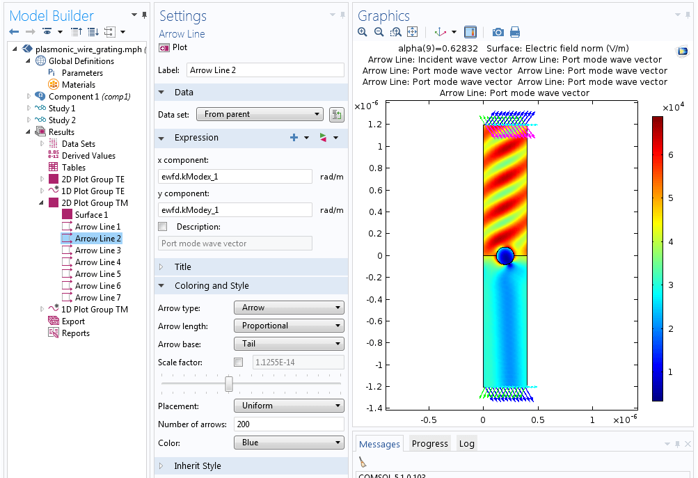
RF Module - COMSOL 5.1 Release Highlights
 www.comsol.com
comsol diffraction grating optics module plasmonic difracción órdenes mostrando flechas gráfico plot
Direct RF: The Transformation Of Critical Defense Systems - Military
 militaryembedded.com
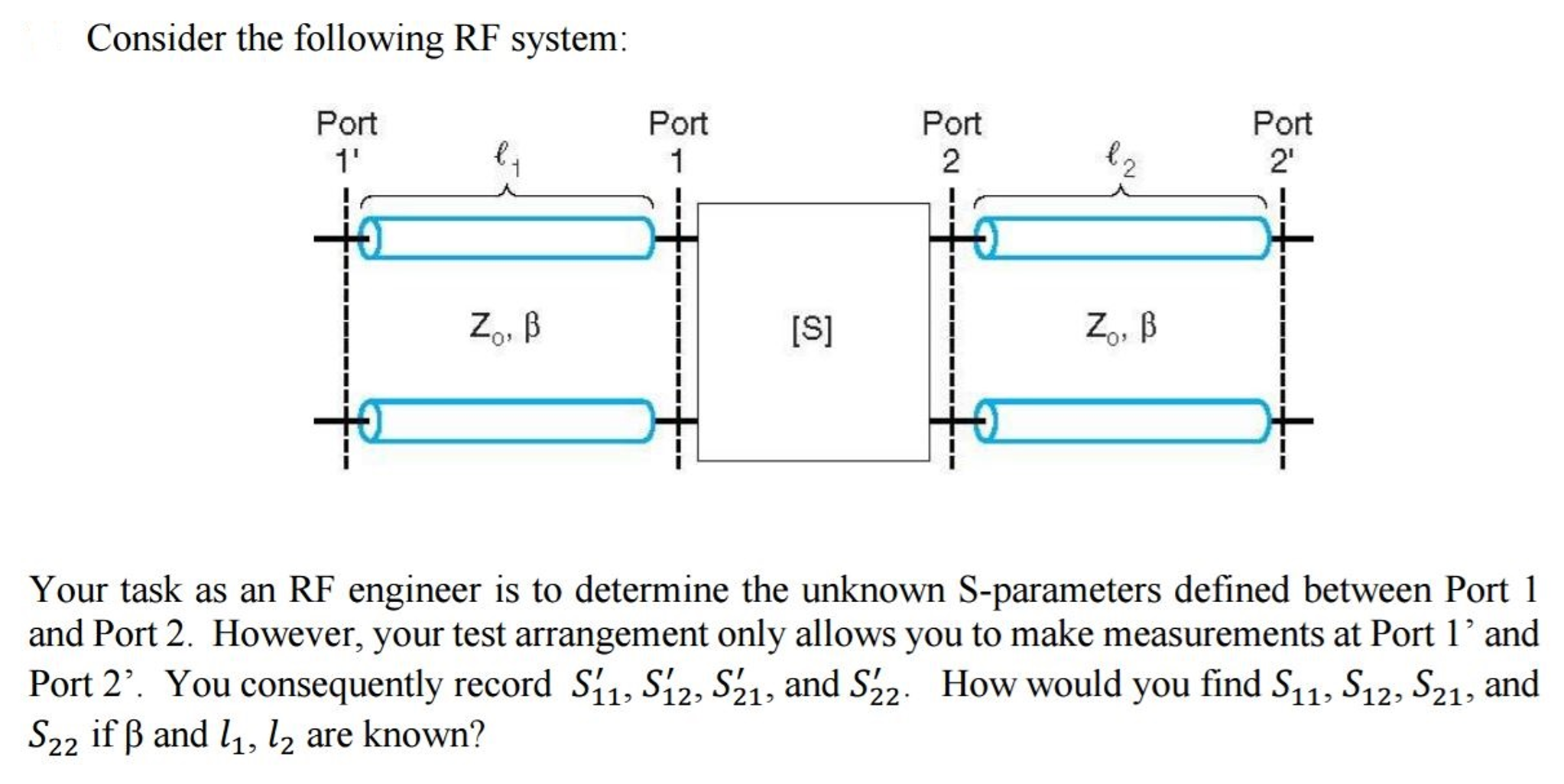
Your Task As An RF Engineer Is To Determine The | Chegg.com
 www.chegg.com
Cross‐sections Of The Receiver Function (RF) Traces Superimposed On The
 www.researchgate.net
(PDF) Extending Dynamic Range Of RF PWM Transmitters
 www.academia.edu
Electrical engineering. Comsol diffraction grating optics module plasmonic difracción órdenes mostrando flechas gráfico plot. Cross‐sections of the receiver function (rf) traces superimposed on the